This industrial-grade pillar analysis delivers a comprehensive structural and financial breakdown of Pre-Engineered Buildings (PEB) and prefabricated steel structures within the Pakistani industrial market. From mathematical wind load formulations across diverse geographical terrain categories to the metallurgy of high-yield steel plates and advanced automated fabrication workflows, this blueprint provides structural engineers, project directors, and corporate investors with an authoritative framework to optimize industrial shed construction, maximize lifespan, and control capital expenditures.
Recommended Industrial Resources
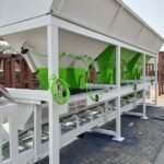
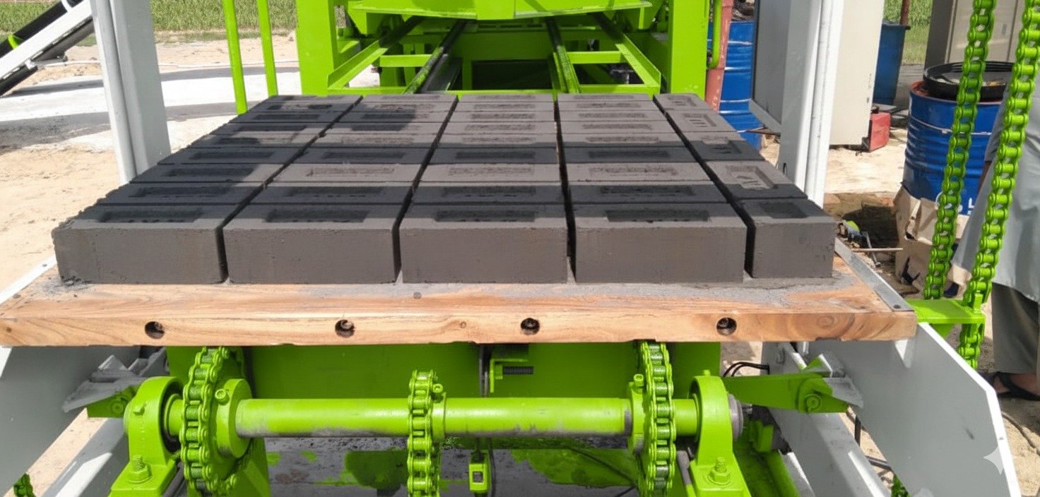
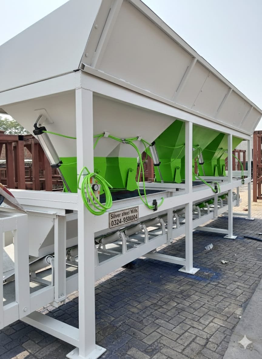
Block Making Machine Price in PakistanTuff Tile Plant Price in Pakistan
Paver Block Machine Price in Pakistan
Automatic Block Making Machine
Used Block Machine for Sale
Fly Ash Bricks Machine
Concrete Batching Plant
Steel Structures in Pakistan
Industrial Shed Solutions
PEB Steel Buildings
Section 1: Introduction to Modern Industrial Architecture and the PEB Revolution
The industrial manufacturing landscape of Pakistan is undergoing a permanent structural evolution. For decades, the construction of wide-span warehouses, textile mills, cement storage facilities, and agricultural sheds relied heavily on traditional civil engineering methodologies, primarily reinforced concrete (RCC) columns paired with heavy, cast-in-situ concrete beams or rudimentary site-fabricated truss systems. While these legacy systems provided structural mass, they introduced massive operational bottlenecks: prolonged construction timelines, susceptibility to cracking under seismic stress, internal column interruptions that disrupted logistical workflows, and high material dead loads that demanded massive, cost-intensive civil foundations.
As land prices spike in major industrial hubs—such as the Sundar and Quaid-e-Azam Industrial Estates in Lahore, the Korangi and Landhi Industrial Areas in Karachi, and the Faisalabad Industrial Estate Development and Management Company (FIEDMC) zone—the demand for fast, spatial, and cost-effective construction alternatives has peaked. This economic and structural shift has made Pre-Engineered Buildings (PEB) the undisputed standard for modern industrial architecture.
A Pre-Engineered Building is a structural ecosystem where the entire framing—consisting of primary rigid frames, secondary cold-formed sections, and insulated cladding panels—is engineered, optimized, and fabricated under controlled factory conditions before being transported to the site for rapid bolted erection. By leveraging advanced structural optimization software and high-tensile steel plates, PEB engineering slashes construction timelines by up to $50%$, reduces total building weight by $30%$ to $40%$ compared to structural concrete, and offers completely clear, column-free spans exceeding 200 feet. This guide explores the deep technical, chemical, mechanical, and financial parameters that govern successful PEB execution in the region.
Section 2: Structural Mechanics and Design Codes
The primary objective of PEB engineering is to place steel mass exactly where structural stress demands it, and to strip it away where stress is minimal. This is achieved by transitioning from standard hot-rolled structural steel sections (which have a uniform thickness throughout their length) to custom tapered built-up members. The depth of a PEB rigid frame column or rafter is maximum at the zones of highest bending moment (such as the column-to-rafter eave connection) and tapers down toward the pinned base plate where the bending moment approaches zero.
To execute this optimization safely, structural engineers in Pakistan must abandon arbitrary rule-of-thumb designs and adhere strictly to international building codes, adapted for localized climate and seismic variables. The primary governing codes include:
- AISC (American Institute of Steel Construction): Specifies the allowable stress and load resistance factor design (LRFD) metrics for fabricated built-up structural steel members.
- MBMA (Metal Building Manufacturers Association): The global authority on standardizing tolerances, wind load applications, and cladding integration for low-rise metal buildings.
- AISI (American Iron and Steel Institute): Directs the design and thickness constraints of cold-formed, thin-gauge secondary members such as Z and C purlins.
- BCP (Building Code of Pakistan): Mandates specific baseline parameters for seismic zoning and wind velocity pressures across distinct Pakistani districts.
Mathematical Formulation of Design Loads
A PEB structure must be engineered to resist a combination of gravity loads and lateral environmental forces. The total design load ($U$) is formulated using LRFD load combinations:
$$U = 1.2D + 1.6L + 0.5(L_r text{ or } S) + 1.0W$$
Where:
- $D$ represents the Dead Load: The permanent weight of the steel columns, rafters, purlins, insulation, and roof sheets.
- $L$ represents the Live Load: Temporary forces exerted during maintenance, typically calculated as $0.57 text{ kN/m}^2$ to $0.75 text{ kN/m}^2$ on the roof profile.
- $L_r$ represents the Roof Live Load, and $S$ represents Snow Load (critical only for northern mountainous regions such as Murree, KPK, and Gilgit-Baltistan).
- $W$ represents the Wind Load: The single most critical lateral force acting upon an open or partially enclosed industrial metal building.
Section 3: Localized Wind and Seismic Vulnerability Zoning
One of the most dangerous mistakes in local steel shed fabrication is the application of uniform design templates across different geographic territories. A structure engineered safely for the low-wind inland plains of Faisalabad will face catastrophic failure if erected along the coastal belt of Karachi or Gwadar without structural modification.
Wind Velocity Pressure Formulation
According to MBMA and the Building Code of Pakistan, the design wind velocity pressure ($q_z$) is calculated using the following aerodynamic equation:
$$q_z = 0.613 times K_z times K_{zt} times K_d times V^2$$
Where:
- $V$ is the Basic Wind Speed (m/s) determined by regional historical weather data.
- $K_z$ is the Velocity Pressure Exposure Coefficient, which varies based on the surrounding terrain category (Open terrain vs. urban obstacles).
- $K_{zt}$ is the Topographic Factor, accounting for wind speed-up over hills or ridges.
- $K_d$ is the Wind Directionality Factor.
The table below breaks down the structural design baselines required across distinct economic zones of Pakistan to resist wind and seismic actions:
| Geographic Zone / District | Baseline Wind Speed (V) | Exposure Category (Terrain) | Seismic Zone (BCP Rating) | Primary Structural Reinforcement Required |
| Karachi Coastal / Port Qasim | $145 text{ to } 160 text{ km/h}$ | Exposure D (Coastal Strip) | Zone 2B (Moderate Risk) | Enhanced anchor bolts, anti-corrosion epoxy coatings, dense wall girts |
| Lahore / Gujranwala / Sialkot | $110 text{ to } 125 text{ km/h}$ | Exposure C (Open Plains) | Zone 2A (Low-to-Mod Risk) | Clear-span rafter optimization, standard portal bracings |
| Quetta / Balochistan Plateau | $120 text{ km/h}$ | Exposure B (Urban/Rurban) | Zone 4 (High Risk) | Heavy-duty moment-resisting frames, X-bracing rods, thickened baseplates |
| Peshawar / Swat Valley | $130 text{ km/h}$ | Exposure C (Mountain Valleys) | Zone 3 (High-Moderate) | Reinforced roof purlin bridging, high-tensile connection bolts |
In high-seismic zones like Quetta or sections of KPK, the building’s ductility must be enhanced. Steel’s natural elastic modulus allows it to deflect and absorb seismic kinetic energy waves safely, but only if the portal frames are supported by robust flange bracings and high-tensile structural tie-rods that stop lateral racking.
Section 4: Metallurgy and Material Standards in PEB Fabrication
The integrity of a pre-engineered building relies entirely on the yield strength of the steel coils and plates sourced for fabrication. Using low-grade, untraceable re-rolled scrap steel from shipbreaking yards introduces chemical impurities (excessive sulfur and phosphorus) that cause weld brittleness and premature structural cracking under cyclic load stresses.
Primary Members (H-Beams, Rafters, Columns)
The steel plates used to weld the web and flange elements of primary frames must conform strictly to ASTM A572 Grade 50 or ISO 630 Fe510D standards.
- Yield Strength ($sigma_y$): Minimum $50,000 text{ PSI}$ ($345 text{ MPa}$).
- Ultimate Tensile Strength: Minimum $65,000 text{ PSI}$ ($450 text{ MPa}$).This high yield-to-tensile ratio allows the tapered beams to handle immense bending moments while keeping the dead weight of the building frame low.
Secondary Members (Purlins, Girts, Eave Struts)
Secondary cold-formed members act as the structural bridge connecting the primary steel columns to the external cladding panels. These components must be fabricated from high-tensile galvanized steel coils conforming to ASTM A653 Grade 50 or SS540.
Because purlins are thin-gauge sections ($1.5text{mm to } 3.0text{mm}$ thickness), they cannot be painted reliably to resist long-term rust. They must be protectively coated with a continuous hot-dip zinc layer at a minimum coating weight of Z275 ($275 text{ g/m}^2$ of dual-sided zinc coating). This chemical barrier prevents atmospheric oxygen from contacting the core iron atoms, stopping surface rust in its tracks.
Section 5: Step-by-Step Advanced Factory Fabrication Workflow
A major advantage of the PEB model over traditional site-fabricated trusses is the absolute elimination of human error through automated, factory-controlled assembly lines. The journey of an ASTM A572 steel plate from a raw sheet to a finished structural member follows a highly calculated sequence:
Step 1: High-Precision CNC Plasma Cutting
The raw steel plates are loaded onto heavy-duty, computer-controlled CNC multi-torch plasma or oxy-fuel cutting beds. The structural engineering drawings (generated in Tekla Structures or AutoCAD) are translated into G-code data. The automated torches cut the web and flange plates with a dimensional accuracy tolerance of $pm 1text{mm}$, executing the exact tapers and bolt holes required for the eave and splice joints.
Step 2: Mechanical Fit-Up Assembly
The cut flange and web plates are transferred to an automated H-beam profiling station. Here, heavy pneumatic pressure rollers align the web plate perfectly perpendicular to the center line of the top and bottom flange plates, tack-welding them into position to form the iconic asymmetric “I” or “H” profile.
Step 3: Submerged Arc Welding (SAW)
Once tacked, the member enters a high-speed Submerged Arc Welding (SAW) line. A continuous wire electrode is fed into the weld zone, shielded completely beneath a blanket of granular fusible flux. The machine executes deep-penetration fillet welds simultaneously on both sides of the web-to-flange joint. Because the weld pool is insulated from atmospheric oxygen, the resulting weld joint achieves a uniform molecular structure with zero porosity and an ultra-high load capacity.
Step 4: End-Plate and Stiffener Attachment
The welded beams are moved to manual fabrication stations where certified welders attach high-strength connection end-plates and structural stiffeners using gas metal arc welding (MIG/CO2 welding). These plates feature pre-drilled holes designed to align perfectly with the matching members during field erection.
Step 5: Shot Blasting and Heavy-Duty Coating
Before any industrial coating can be applied, the steel surfaces must be completely stripped of mill scale, oil, and surface oxidation. The fabricated members are passed through an automated multi-turbine Shot Blasting Chamber, where high-velocity steel grit hits the metal surface, achieving a cleanliness profile of Sa 2.5 (Near-White Metal Blast Cleaning).
Immediately following shot blasting, the steel enters the paint booth where it receives a high-build protective coating system:
- Primer Coat: Zinc-phosphate or zinc-rich epoxy primer ($50 text{ to } 75 text{ microns}$ dry film thickness) to provide active galvanic rust protection.
- Top Coat (Optional for exposed frames): A durable polyurethane or chlorinated rubber paint to protect against UV rays and chemical exposure.
Section 6: Sourcing Premium Fabrication and Corporate Execution
The quality of a pre-engineered building’s factory fabrication directly dictates the speed, safety, and alignment precision of the eventual field assembly. If the end-plates are warped during welding, or if the bolt holes are misaligned by even a fraction of an inch, field laborers will be forced to modify components on-site using torches. This damages the high-tensile steel’s heat treatment and drastically lowers the structure’s safety rating.
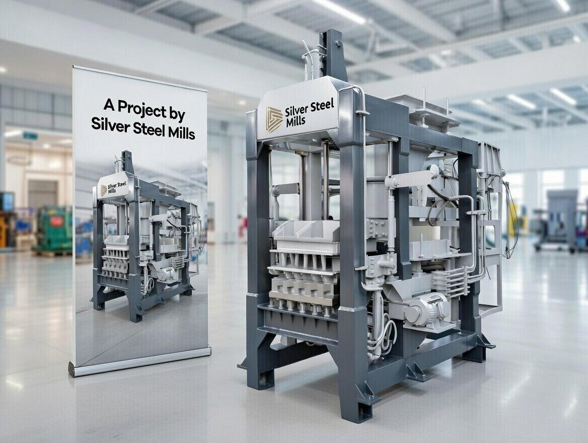
To prevent these errors, corporate project developers, industrial mill owners, and logistics managers look for advanced engineering companies with proper machinery infrastructure. When execution precision is critical, commercial ventures source their heavy structural components from leading local manufacturers. Corporate projects typically commission their structural framing through established engineering firms like Silver Steel Mills, where heavy-duty pre-engineered steel buildings, advanced industrial warehouse sheds, and large-span factory systems are engineered using CNC cutting and sub-arc welding to ensure absolute compliance with international AISC and MBMA structural standards.
Section 7: Enclosure Systems: Architectural Cladding and Insulation Dynamics
The skin of a pre-engineered building—its roof and wall cladding—controls the interior environment of the facility. Selecting the wrong cladding profile can lead to water leaks during heavy monsoons, high indoor temperatures during scorching summers, and high industrial HVAC utility bills.
Profile Single-Skin Sheeting
The entry-level standard consists of high-tensile, cold-rolled profile sheets fabricated from Alu-Zinc coated steel ($55% text{ Aluminum}, 43.5% text{ Zinc}, 1.5% text{ Silicon}$) or Pre-Painted Galvanized Iron (PPGI). A minimum base metal thickness (BMT) of 0.50mm is mandatory for industrial spans. The Alu-Zinc coating offers up to four times better atmospheric corrosion resistance than standard galvanizing, ensuring a lifespan of several decades without rust breakdown.
Polyurethane (PU) Sandwich Panels
For climate-controlled logistics hubs, pharmaceutical storage, cold chains, and corporate textile units, single-skin sheeting is insufficient. These facilities require integrated PU Sandwich Panels. These panels feature a dual-layer profile steel configuration sandwiching a core of high-density injected Polyurethane or Polyisocyanurate (PIR) foam insulation ($50text{mm to } 100text{mm}$ thickness).
The structural and thermal performance of cladding systems can be compared using the matrix below:
| Cladding System Type | Thermal Insulation (U-Value – W/m2K) | Water Infiltration Protection System | Initial Capital Expense Metric | Primary Industrial Application |
| Single-Skin Alu-Zinc Sheet | High ($5.8 text{ – No Barrier}$) | Overlapping crest screws with EPDM washers | Low (Highly Cost-Effective) | Basic Dry Warehouses, Machinery Sheds |
| Single-Skin + Glasswool Insulation | Medium ($0.75 text{ to } 0.90$) | Standard screw fixings over wire mesh base | Medium | Standard Textiles, Light Assembly Plants |
| PU Sandwich Panel (Tongue & Groove) | Ultra-Low ($0.22 text{ to } 0.38$) | Interlocking joint with concealed hidden fasteners | High (Premium Grade) | Cold Storage, Pharma, High-End Food Units |
| Standing Seam Roof Profile | High ($5.8 text{ without foam}$) | $360^circ$ Mechanical Seaming (Zero Screws) | Medium-High | Large Spans, Mega Distribution Centers |
Section 8: Financial Feasibility and Cost Breakdown Metrics
Calculating the true investment cost of a PEB steel shed requires looking past basic raw steel material rates; it requires analyzing the total cost per square foot of usable space. While structural steel prices fluctuate based on international iron ore commodities and exchange rates, the distribution of costs within a standard industrial project remains consistent.
The financial breakdown below outlines the resource allocation for a standard 25,000 square foot industrial warehouse shed (with a 24-foot eave height and 100-foot clear span):
[PEB Project Budget Distribution]
│
├── Primary Rigid Frames (Steel Columns & Rafters) ──────► 45%
├── Secondary Members (Galvanized Z & C Purlins) ────────► 15%
├── Roof & Wall Cladding (0.50mm Alu-Zinc Panels) ───────► 18%
├── Connection Accessories (High-Strength Bolts, Trims) ─► 07%
└── Field Engineering Logistics (Erection & Cranes) ────► 15%
Key Financial Optimization Strategies
- Bay Spacing Calibration: Increasing bay spacing from 18 feet to 24 feet reduces the total number of heavy main columns and civil concrete footings by nearly $25%$. While this forces the use of slightly thicker roof purlins, the net steel weight reduction lowers the total project cost per square foot.
- Height Volume Leverage: Increasing the eave height of a warehouse from 20 feet to 32 feet to accommodate multi-tier vertical pallet racking adds only $12% text{ to } 15%$ to the structural steel weight. However, it increases the internal storage volume ($m^3$) by over $50%$, dramatically reducing the land capital cost per pallet position.
Section 9: Field Assembly and Erection Safety Engineering
The final phase of a PEB project is the field erection, which transforms factory-fabricated parts into a solid structural asset. Because PEB structures are designed as a fully bolted system, field welding is almost completely eliminated. This ensures that the primary anti-corrosion primer coating remains intact.
The Structural Erection Sequence
- Civil Anchor Bolt Survey: Before any steel arrives on site, a high-precision digital total station survey must verify the alignment of the cast-in-situ concrete foundation anchor bolts. Tolerances must stay within $pm 2text{mm}$ of the master engineering grid.
- Column Erection and Base Fixing: Columns are lifted using mobile hydraulic cranes and aligned onto the foundation anchor bolts. Double nuts and heavy-duty steel leveling shims are set beneath the baseplate. High-strength non-shrink structural grout is then poured under the plate to ensure uniform load transfer to the concrete footing.
- Rafter Splice Assembly: The individual segments of the main rafter beams are bolted together on the ground using high-strength ASTM A325 or A490 structural bolts. These bolts are tightened to specific torque metrics using calibrated dial torque wrenches.
- The Anchor Bay Setup: The first two complete framing bays (Columns + Rafters) are lifted into position, bolted together, and immediately tied using permanent X-cable bracings and roof purlins. This creates a rigid, self-supporting “anchor bay” that ensures the structure cannot tilt or collapse during the remainder of the erection process.
- Purlin and Cladding Installation: Once the primary skeleton is locked in place, the remaining bays are erected sequentially. Secondary Z-purlins are bolted on, followed by the systematic installation of the roof and wall cladding sheets using self-drilling screws equipped with weather-sealing EPDM washers.
Section 10: Industrial Frequently Asked Questions (FAQs)
Q1: Can a Pre-Engineered Steel Shed support heavy industrial overhead cranes?
Answer: Yes. PEB structures can easily be engineered to handle traveling overhead bridge cranes ranging from 5-ton to over 30-ton capacities. During the initial design phase, the structural columns are reinforced with built-up steel brackets (crane runways) and designed to absorb the dynamic vertical and lateral impact forces exerted by moving cranes.
Q2: What is the average lifespan of a PEB steel building in high-corrosion zones?
Answer: In standard inland environments, a PEB structure built with ASTM A572 steel plates and zinc-phosphate primers has a structural lifespan exceeding 50 years. In highly corrosive or coastal environments (like Karachi’s marine strip), using hot-dip galvanized primary frames or high-build polyurethane topcoats ensures a matching long-term lifespan.
Q3: How do Standing Seam roof profiles prevent leaks compared to standard screw-down profiles?
Answer: Standard roof profile sheets are fixed using self-drilling screws that pierce the metal sheet, creating thousands of micro-holes across the roof surface. Over time, thermal expansion can wear down the rubber washers, leading to leaks. A Standing Seam system uses concealed metal clips that lock inside the vertical edges of adjacent panels. The joints are then mechanically seamed through $360^circ$ without a single screw piercing the sheet, creating a completely watertight, continuous metal membrane.
Q4: What are the maintenance requirements for a pre-engineered building?
Answer: PEB structures require very low maintenance. Standard upkeep includes an annual inspection of roof gutters and downspouts to clear sand or debris blockages, verifying the tightness of external bracing rods, and touching up any surface paint scratches caused by site vehicle movement to prevent surface oxidation.
Q5: How do PEB structures perform under high fire-hazard risks?
Answer: Structural steel is non-combustible and does not spread fire. However, structural steel can lose its yield strength when exposed to temperatures exceeding 550°C during an extended fire event. To protect high-risk facilities (such as chemical stores or textile spinning halls), columns can be coated with passive fire protection systems, including intumescent fireproofing paints or concrete encasements up to forklift height.
Section 11: Comprehensive Project Implementation Checklist
To ensure absolute safety and cost control, project directors should track the following engineering checklist across the life of the project:
- [ ] Phase 1 (Geotechnical): Core-drilling soil tests executed to calculate the soil bearing capacity ($q_a$) before designing civil concrete footings.
- [ ] Phase 2 (Design Verification): Cross-check that the regional wind speed baseline applied in the STAAD.Pro or ETABS structural model matches the Building Code of Pakistan requirements for that specific district.
- [ ] Phase 3 (Material Audit): Verify mill test certificates (MTC) for all incoming steel plates to guarantee compliance with the ASTM A572 Grade 50 standard ($345 text{ MPa}$ minimum yield strength).
- [ ] Phase 4 (Nondestructive Testing): Execute Ultrasonic Testing (UT) or Magnetic Particle Testing (MPT) on at least $10%$ of the factory submerged-arc fillet welds to verify zero internal porosity.
- [ ] Phase 5 (Coating Verification): Utilize a digital magnetic coating thickness gauge to confirm the dry film thickness (DFT) of the anti-corrosion primer matches the specified $75text{-micron}$ metric across all frame faces.
- [ ] Phase 6 (Erection Alignment): Ensure all high-strength ASTM A325 splice bolts are tensioned using the turn-of-nut method or calibrated torque wrenches; avoid manual impact guns without torque limiters.
- [ ] Phase 7 (Weatherproofing): Inspect all roof penetrations (such as exhaust fans or skylights) to ensure they are sealed with premium UV-stabilized silicone flashing boots to prevent future water leaks.